Nov 27, 2015

A quick HUB08 LED Matrix Library & Graphics Library

I recently got an LED Matrix using the HUB08 protocol from ebay. Since none of the libraries I found on the internet worked for me, I wrote my one for the Arduino Uno, using hardware SPI. It also supports pwm brightness control and frame rates up to 2000 fps (32kHz line frequency, 16 lines). Yeah, that's fast, so the microcontoller can do other stuff in between (instead of really working with such ridiculous frame rates ;) ). The pins are hard coded into the library to achieve this speed. Please take a look at the example to understand how to connect the matrix and how to use it, it's pretty simple.
Link to github: https://github.com/emgoz/HUB08SPI

I also want to share another library with you, the Buffer Graphics Library. It features many optimized drawing functions (points, lines, rectangles, circles, bitmaps)  and buffer manipulation functions (scrolling, rotating, flipping, ...) and also works with the matrix library above quite nicely.
Link to github: https://github.com/emgoz/BufferGraphics
-Marv

Jun 4, 2015

Simple Programming Adpter for Arduino Pro Mini

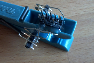
I ordered a bunch of these little Arduino Pro Mini Clones that just have anything to get started right away with your projects in need of a simple micro controller breakout. Sadly, they come with the standard Arduino bootloader which delays the programm start about 2 seconds everytime the board is powered up. So I wanted to update to optiboot, a great alternative to the original bootloader and also saves a few bytes flash. The standard way to do that is with an In-System-Programmer. The board hasn't got an ISP socket to reprogram it, so usually you just solder wires or pin headers to pins 11,12,13, RST, VCC and GND to hook it up to the programmer. However, I don't know what I want to do with most of the boards and it might be handy some time that there no bulky headers attached it. So I remembered those clip programming adapters and tried to built one with junk I had lying around: A peg, a piece of a zip tie, some regular PCB headers and hot glue. I had some doubts whether the contacts were good enough, but it worked surprisingly well!


- Marv

Apr 18, 2015

Quirks with YET-M1 and USB-Ports

A few days ago, I ordered a YET-M1 Bluetooth Audio Adapter for just a few bucks on ebay. It has a 3.5 mm jack as audio output, you can simply hook it up to any active speaker and make it bluetooth enabled. It can so play the music from your phone wirelessly. It is powered over the USB-plug on the other end, so you just need to plug it in your phone charger.


Well, then I tried it out with an AV receiver, which even has a convenient USB port for flash drives already build in. However, the bluetooth adapter seemed like it didn't power up. The same happened with another hi-fi system's USB port. However, when powered with a phone charger or by directly applying 5V to the GND and +5V lines of the USB plug, it worked. My first guess was, that those USB ports don't output enough power for the adapter. This was easily disproved by being able to charge my phone over this port. I measured the voltage on the two power lines: 5V. So this should be alright.
Apparently it had something to do with the data lines. I opened the adapter to have a look at those and indeed, they where connected to the bluetooth chip. Maybe for configuration/programming in the factory. It seemed like this is is what pees on the parade. The AV receiver tries to communicate with the adapter and thereby freezes it.
Unsoldering the plug and bending over the data lines to disconnect them is what fixes the problem.
<s> Is that really what the manufacturer expects us to do? </s>

- Marv

Apr 2, 2015

Yet Another WS2812 library

I'm currently working with the WS2812 LEDs. They are awesome because they're so simple to hook up and interface with.
Probably the most popular Arduino library for programming these LEDs is FastLED. It features a ton of useful functions and super optimized routines. And you cannot only use LEDs with the WS2811 controller, also SPI based controllers. However, I failed getting it to work with a 8 MHz AVR.  It seemed like the timing was way off.

Edit: It is the ATmega 1284P that will cause problems with FastLED. Apparently the bit-banging-routines are only working on 328, 32u4 and 2560. This is due to the larger memory the 1284P can access, which needs 3 address bytes instead of 2 with the 328. Therefore, jump-instructions take one tick longer. At 8 MHz that is 0,125 µs which is 10% of the period of one bit at 800 kHz (the clock frequency of the WS2812). That's why the actual clock frequency of the AVR needs to be 10% higher than defined in the F_CPU macro. According to this, the developers of FastLED are aware of this issue, but are not going to fix it.

Over at the Arduino forums, someone recommended using a light weight WS2812 library instead. I tried this one and it worked like a charm. Unfortunately, it is so "light" that it doesn't even support a global brightness parameter. Also, the way the HSV to RGB conversion is a bit user-unfriendly by using an indirection with another RGB-struct.

So I changed the whole library by Tim aka cpldcpu, Matthias Riegler, Windell H. Oskay and Freezy a bit up. I added direct RGB and HSV access to each pixel, the optimized HSV to RGB function from FastLED and a global brightness method, which is defeatable by commenting out a single line (to make it lighter for ATtiny). It isn't beautiful, but it works and some of you might be interested in it, so I shared it.
https://github.com/emgoz/WS2812
- Marv

Mar 26, 2015

Enlarge I²C Device Count with Chip Selects?

This is only a quick write up on my idea, and I haven't got the time to include a few illustrations / schematics to state my point. If it is too long for you to read, only focus on the last paragraph which describes the solution.

Introduction

I²C is great, probably the simplest way to hook up peripherals to a microcontroller. You only need two connect two wires to the device you want to interface with - clock and data. These two wires are shared between all the I²C devices. To select a specific device to talk to, the 7 bit address is sent to all the devices on bus, those compare this address to their own and only the one with the same address becomes active. This way, it is possible to interface with up to 112 (2^7 minus 16 reserved addresses) I²C devices on one bus. Sounds like that's a lot, but what when you cannot use them all?
While working on a new project, I stumbled upon a problem: I want to have a lot of the same I²C device on one bus. Well, usually the manufacturer of the peripheral ensures the possibility to select the address - or a part of the address - by offering one or more address select pins. There are a lot of different approaches on how to select the address:
  • Tie the pin to GND or VCC (-> one address Pin doubles the amount of possible devices)
  • Leave the pin open or use one of the above  (-> one address Pin triples the amount of possible devices) 
  • Tie the pin SDA, SCL, GND or VCC  (-> one address Pin quadruples the amount of possible devices) 
  • Tie the pin with a specific resistor to Ground  (-> usually up to 4 or 5 possibilities)
In most cases, this is absolutely sufficient. However, I wanted to connect 5 MPR121 for a lot of capacitive sensors and this chip offers only one address select pin (using the third approach I described above) for up to 4 different addresses. I am sure that other people encountered a similar problem so I did some research. These are some of the options I found: